IPC TM 650 for Beginners: A Hobbyist's Guide to Basic PCB TestingAuthor : Adrian October 10,difference between solder paste and flux 2025Table of ContentsIf you're a hobbyist diving into the world of printed circuit boards (PCBs), you might have come across the term IPC-TM-650. But what exactly is it, and how can it help you with your DIY projects? In simple terms, IPC-TM-650 is a set of test methods created by the Institute of Printed Circuits (IPC) to ensure the quality and reliability of PCBs. For beginners, it offers a roadmap to test your boards effectively, even with limited resources. In this guide, we’ll break down IPC-TM-650 simplified, explore basic PCB tests for hobbyists, and share DIY PCB testing methodsusing low-cost PCB testing equipment. Let’s also dive into understanding IPC standards for home projectsso you can build better, more reliable circuits.
What is IPC-TM-650 and Why Should Hobbyists Care?IPC-TM-650 is a comprehensive manual of test methods developed by the IPC, an organization dedicated to setting standards for the electronics industry. This manual covers a wide range of tests to evaluate the performance, durability, and quality of PCBs. These tests are grouped into categories like visual inspection, mechanical testing, electrical testing, and environmental testing. While it’s primarily used by professionals in large-scale manufacturing, hobbyists can benefit from understanding and applying these methods on a smaller scale. As a hobbyist, you might wonder why you need to bother with such standards. The answer is simple: testing your PCB ensures it works as intended and lasts longer. Even a small flaw, like a weak solder joint or a misaligned trace, can cause your project to fail. By following simplified versions of IPC-TM-650 tests, you can catch these issues early, saving time and money. Plus, learning these standards gives you a glimpse into professional practices, helping you improve your skills.
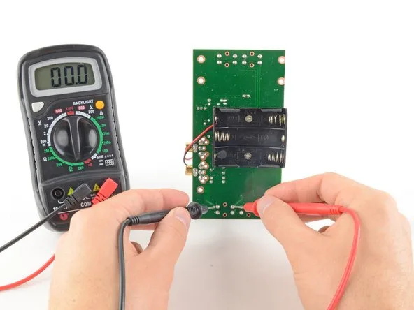
Breaking Down IPC-TM-650: Key Categories for HobbyistsThe IPC-TM-650 manual is vast, with over 100 test methods, but not all are relevant for home projects. Here, we’ll focus on the most practical categories for hobbyists and how you can apply them with limited equipment. 1. Visual Inspection (Section 2.1)Visual inspection is the first and simplest step in PCB testing. IPC-TM-650 provides guidelines on what to look for, such as cracks in the board, uneven solder joints, or misaligned components. For hobbyists, this means using your eyes or a magnifying glass to check for obvious defects. How to Do It:Hold your PCB under good lighting and examine it closely. Look for scratches on the copper traces, which should appear smooth and consistent (typically 1-2 oz copper thickness, or about 35-70 micrometers). Check if solder joints are shiny and rounded, not dull or cracked. If you spot a problem, it could indicate a manufacturing error or poor soldering technique. Tools Needed:A magnifying glass (costing around $5-10) or a low-cost USB microscope (around $20-30) can make this process easier. 2. Dimensional Measurements (Section 2.2)This category involves checking the physical dimensions of your PCB, such as the width of traces or the diameter of vias. IPC-TM-650 specifies acceptable tolerances, often in the range of ±0.1 mm for hobbyist-level boards. How to Do It:Use a digital caliper (available for $10-15 online) to measure trace widths or hole sizes. Compare your measurements to your PCB design file. For example, if your design calls for a trace width of 0.3 mm, ensure it’s within ±0.05 mm of that value. Deviations could affect current carrying capacity, typically calculated as 1 amp per 0.025 mm2 of copper cross-section at 35 micrometers thickness. 3. Electrical Testing (Section 2.5)Electrical testing is crucial to ensure your PCB functions correctly. IPC-TM-650 includes methods like continuity testing and insulation resistance testing. For hobbyists, the focus is on basic checks using affordable tools. Continuity Testing:This verifies that electrical paths (traces and vias) are connected as designed. Use a multimeter (priced at $10-20) set to continuity mode. Touch the probes to two points that should be connected; a beep indicates a good connection. If there’s no beep, you might have a broken trace. Insulation Resistance:This checks for unwanted connections (shorts) between traces. Set your multimeter to resistance mode and test between adjacent traces. A reading above 10 megaohms is generally acceptable for most hobbyist projects, indicating no short circuit. 4. Environmental Testing (Section 2.6)Environmental tests assess how your PCB holds up under stress like heat or humidity. While IPC-TM-650 uses advanced equipment for thermal cycling (e.g., -40°C to 125°C), hobbyists can simulate basic conditions at home. How to Do It:Place your PCB in a warm area (like near a heater at 50-60°C) for a few hours, then check for warping or delamination. For humidity, leave it in a damp environment (like a bathroom after a hot shower) and inspect for corrosion on traces or components. These aren’t precise tests, but they give you an idea of durability.
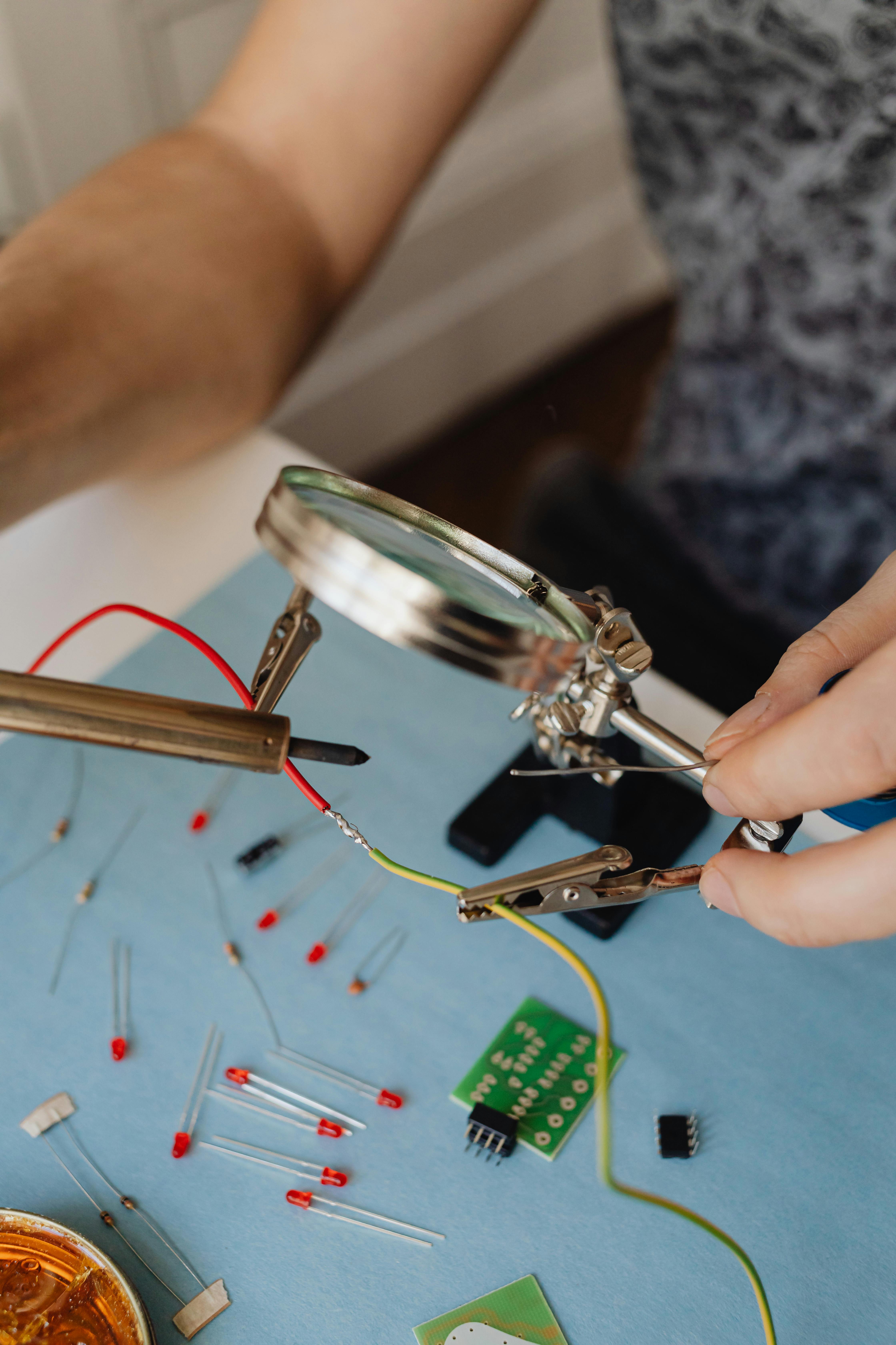
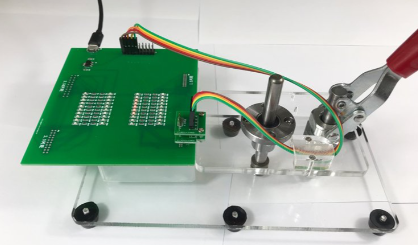
DIY PCB Testing Methods for HobbyistsWhile professional labs use expensive gear to follow IPC-TM-650, hobbyists can adapt these methods with DIY PCB testing methodsand low-cost PCB testing equipment. Here are some practical approaches to get started. Building a Basic Test SetupYou don’t need a fancy lab to test your PCBs. A basic setup can include:
With a total investment of under $100, you can perform most basic tests outlined in IPC-TM-650. Step-by-Step DIY Testing ProcessFollow these steps to test your PCB at home, inspired by IPC-TM-650 guidelines:
Understanding IPC Standards for Home ProjectsUnderstanding IPC standards for home projectsmight seem intimidating, but it’s about applying the core principles of quality and reliability to your work. Here’s how you can adapt these standards without getting overwhelmed. Focus on Relevant StandardsBesides IPC-TM-650, other IPC standards like IPC-A-600 (for bare board acceptability) and IPC-A-610 (for assembled board acceptability) provide visual and performance criteria. As a hobbyist, you don’t need to follow every detail, but skimming these documents (often available as free summaries online) can teach you what “good” looks like. For example, IPC-A-610 specifies that a solder joint should cover at least 75% of the pad for reliability. Keep It Simple and ScalableYou’re not running a factory, so start with the basics: visual checks, simple electrical tests, and minimal environmental stress tests. As your skills grow, you can invest in better tools or try more complex IPC-TM-650 methods, like thermal stress testing with a controlled oven.
Low-Cost PCB Testing Equipment for HobbyistsTesting doesn’t have to break the bank. Here’s a deeper look at low-cost PCB testing equipmentthat aligns with IPC-TM-650 simplified approaches:
Common PCB Issues Hobbyists Face and How IPC-TM-650 HelpsEven with careful design, PCBs can have problems. Here are common issues hobbyists encounter and how IPC-TM-650-inspired testing can help:
Tips for Success with IPC-TM-650 as a HobbyistTo make the most of IPC-TM-650 in your home workshop, keep these tips in mind:
Conclusion: Elevate Your Hobby with IPC-TM-650As a hobbyist, diving into IPC-TM-650 simplifiedcan transform the way you approach PCB projects. By mastering basic PCB tests for hobbyistsand using DIY PCB testing methodswith low-cost PCB testing equipment, you can build more reliable circuits without a big budget. Understanding IPC standards for home projectsnot only improves your skills but also connects you to the professional world of electronics. Start with the basics—visual checks, simple measurements, and electrical tests—and build from there. With practice, you’ll create PCBs that stand up to real-world use, all while following proven industry methods. At ALLPCB, we’re passionate about supporting hobbyists and professionals alike in their electronics journey. Whether you’re testing a simple prototype or a complex design, applying these principles ensures quality every step of the way. Share · · · · The Role of Flux in PCB Wave Soldering: Selection, Application, and Residue RemovalMarch 16, 2026PCB wave soldering flux types include rosin, water-soluble, and no-clean options with varying activity levels for oxide removal and solder flow. This guide covers selection criteria, spray foam drop-jet application methods, residue removal processes, and alternatives like nitrogen blanketing to boost joint reliability and yields for engineers. Article Achieving Uniform Solder Fillets in PCB Wave Soldering: Process ControlMarch 16, 2026Achieve uniform solder fillets in PCB wave soldering with process control strategies. Optimize flux, preheat, wave height, conveyor speed for consistent fillet shape, height, and wetting balance. Includes visual inspection tips and troubleshooting for reliable through-hole assemblies. Boost quality in production. Article Optimizing Conveyor Speed for Efficient PCB Wave SolderingMarch 16, 2026Learn PCB wave soldering conveyor speed calculation to manage dwell time, immersion depth, and throughput effectively. Electric engineers get practical steps, best practices, and troubleshooting tips for higher process efficiency and fewer defects in wave soldering operations. Article Understanding IPC Standards for PCB Surface Finishes: Ensuring Quality and ComplianceMarch 11, 2026Understand IPC standards IPC 4552 ENIG and IPC 4553 immersion silver for PCB surface finishes. Ensure compliance, enhance solderability, and prevent common defects to achieve reliable, high quality circuit boards. Article Miniaturization Challenges in PCB AssemblyMarch 11, 2026Navigate the complexities of high density interconnect PCB assembly and precise component placement. Learn to tackle miniaturization challenges, from tiny part handling to thermal stress, ensuring robust and reliable electronics. Article High Speed Routing Techniques: PCBMarch 11, 2026Master high speed routing in PCBs to ensure signal integrity and minimize electromagnetic interference. Learn essential techniques for robust designs, from controlled impedance to differential pair strategies. Prevent performance issues and achieve reliable electronics. ArticleGet Instant PCB |